CLR-V300-[4/8]PNVR4
This box includes
-
USB mouse
-
Power cord
Anatomy
-
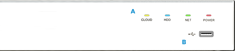
Indicator LEDs – Check the operational status of the device. See below for details on each LED.
-
Front USB port
-
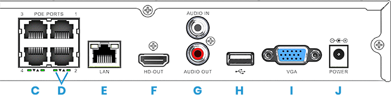
Camera ports – Either 4 or 8, depending on model. Only plug cameras into these ports; never connect a switch.
-
Link/Activity LED: See below for details.
-
Network RJ45 port – Connect to a router or switch for IP control and monitoring.
-
HDMI port – For local minitoring.
-
Audio ports – White is audio input for a microphone, and red is audio output for a speaker.
-
Rear USB port.
-
VGA connector – For local monitoring.
-
Power inlet.
LED indicators
|
Label |
Light |
Meaning |
|---|---|---|
|
Cloud |
Amber (solid) |
Communication with P2P server is operating properly. |
|
Off |
The NVR cannot communicate with P2P server. |
|
|
HDD |
Blue (flashing) |
The hard drive is operational. |
|
Off |
No hard drive is detected. |
|
|
Net |
Green (solid) |
The network is operating properly. |
|
Off |
The NVR cannot communicate with the network. |
|
|
Power |
Red (solid) |
The NVR has power. |
|
Off |
The NVR has no power. |
Installation
The ClareVision NVR is designed to be placed on a shelf.
Connections
-
Connect the NVR's LAN port to a router or switch.
-
If using the local UI,
-
connect the mouse to the rear USB port.
-
connect a monitor to either the HDMI port or VGA port.
-
connect a microphone to the audio in (white), and a speaker to audio out (red).
-
-
Connect the NVR to power. We recommend using a WattBox PDU to protect the NVR.
-
Connect the cameras to the camera ports.
Claim with OvrC
-
Once the NVR has finished booting (about 30 seconds), OvrC should claim it automatically. If not, claim the NVR manually, as follows:
-
Scan the QR code on the top of the NVR. This reveals its serial number. Skip to step e.
-
If the external sticker is missing or damaged, use a browser to navigate to the NVR's IP address. This opens its local interface.
-
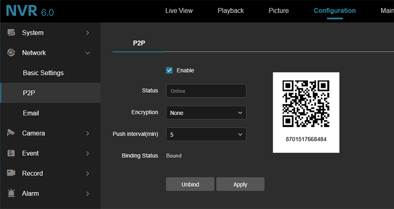
At the left, click the P2P page.
-
Across the top, click the Configuration tab. The serial number displays below the QR code.
-
Navigate to app.ovrc.com and log in.
-
Claim the NVR using its MAC address and serial number.
-
-
Use OvrC to update the NVR firmware if necessary.
-
OvrC auto-claims all cameras.
-
Use OvrC to update camera firmware.
Initialize the HDDs
The installed SATA hard drive appears in the Disk Management page with the status "Uninitialized". Because the disk is not initialized, the NVR reports 0.000 GB free space, and recording will not begin.
To initialize:
-
Power on the NVR.
-
Log in to the web interface via OvrC.
-
Navigate to Configuration → Storage → Disk Management.
-
Observe the HDD status.
-
Click Initialize if needed,
The system is now ready to be customized.
PoE binding
Cameras connected to an NVR port are not immediately available for online viewing; you must first enable POE Binding.
To initialize:
-
Power on the NVR.
-
Log in to the web interface via OvrC.
-
Navigate to Configuration → Storage → Disk Management.
-
Enable PoE Binding for each NVR port with an attached camera.
-
Click Apply.
The system is now ready to be customized.